[Attachment(s) from ericnc@... [DynoMotion] included below]
I am totally unable to solder wires, I'd do this experiment by placing the 26C32 on a breadboard I've bought and wire it temporarily to the other components.
I'd need some assistance in order to not break things..
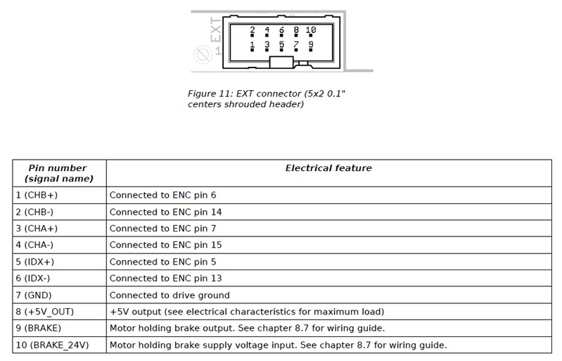
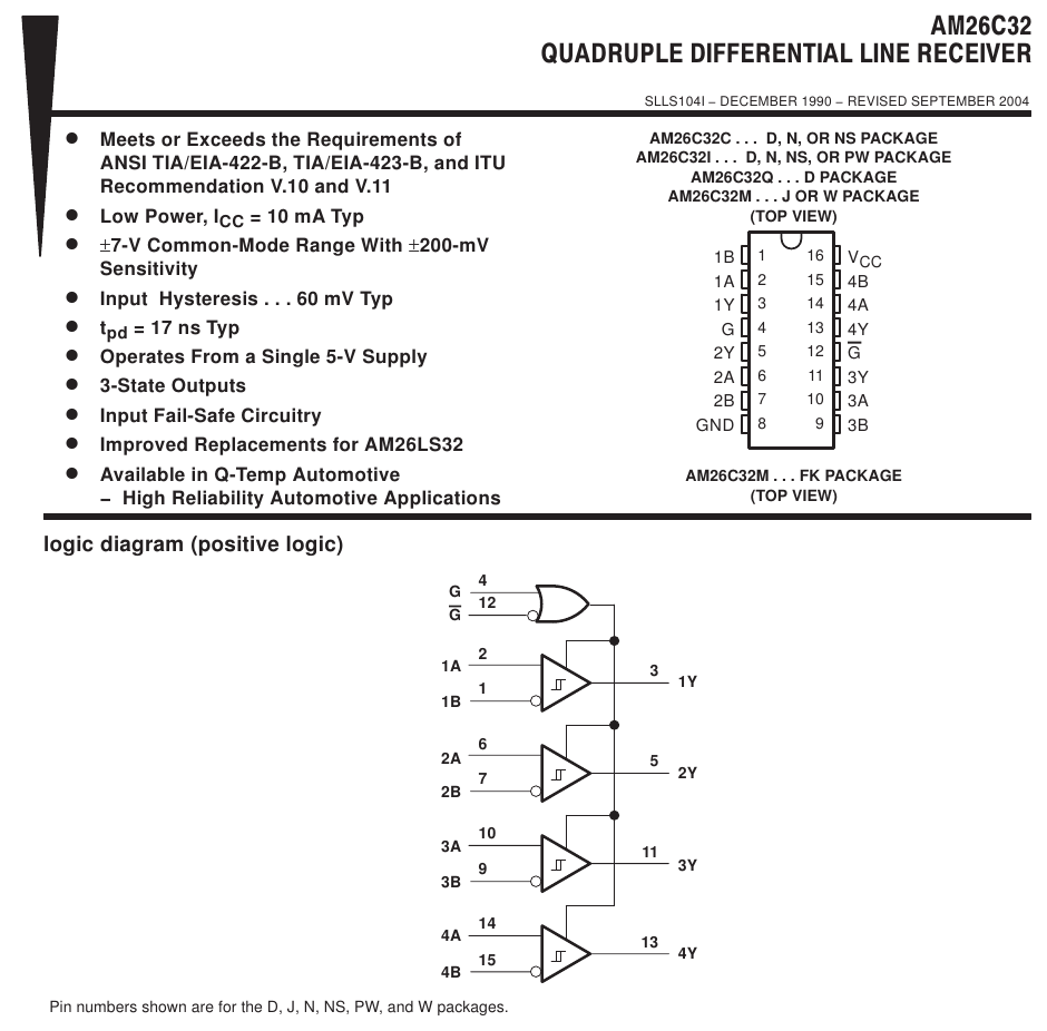
You find attached the pinout of the "EXT" connector on my motor drive (it's a pass-through connector for the encoder signals) and the pinout of the 26C32.
I'd wire things like this:
EXT ___________ AM26C32
1 (CHB+) ...... 6 (2A)
2 (CHB-) ...... 7 (2B)
3 (CHA+) ...... 2 (1A)
4 (CHA-) ...... 1 (1B)
5 (IDX+) ...... 10
(3A)
6 (IDX-) ...... 9 (3B)
7 (GND)
....... 8 (GND), 12 (G')
8 (+5V_OUT) ... 16 (VCC), 4 (G)
AM26C32 ______ KFLOP JP7
3 (1Y) ...... 7 (IO0)
5 (2Y) ...... 8 (IO1)
AM26C32 ______ KFLOP JP5
11 (3Y) ...... 1 (IO36)
Now, it looks me the KFLOP is missing a ground reference for the A, B, IDX signals so I'd also add:
AM26C32 ______ KFLOP JP7
8 (GND) ...... 25 (GND) or 26 (GND)
Is this correct? I am a bit confused about the JP5 connector.
KFLOP manual says it is intended for communication over a twisted pair cable, but what other signal
should I use to make the twisted pair? And, no
ground?
Or, could I just forget the JP5 and wire the IDX signal to any JP7 pin? Is that software configurable?
Thank you,
EC